Reply With Quote
This is what you will get:
 |
 |


I now have a total of 20 of these things. I have yet to have one fail on me, longest has been in service over 4 years now. Several people have asked me about them, but upon purchase can't quite understand how to wire them. to that end, here is a quick how to.
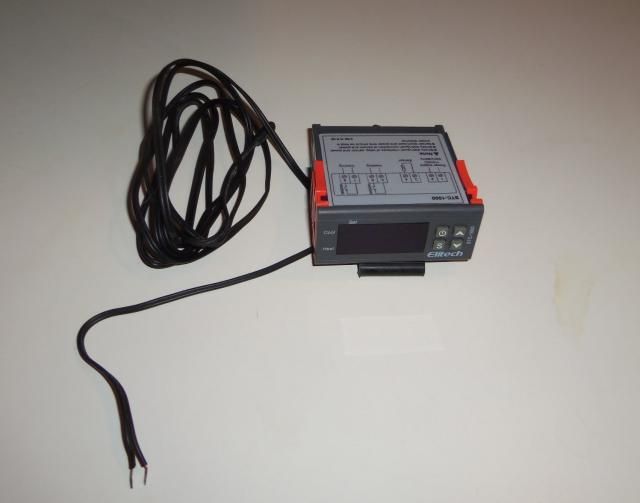
First the controller itself, I get these off of ebay at several different sellers. If you search ebay for "stc-1000" you will find several.
here are a couple of links:
http://www.ebay.com/itm/110V-10A-Min...item461c6cc468
http://www.ebay.com/itm/US-All-Purpo...item4182e2e190
Ex-President-North American Discus Association-NADA
[SIGPIC][/SIGPIC]
This is what you will get:
Ex-President-North American Discus Association-NADA
[SIGPIC][/SIGPIC]
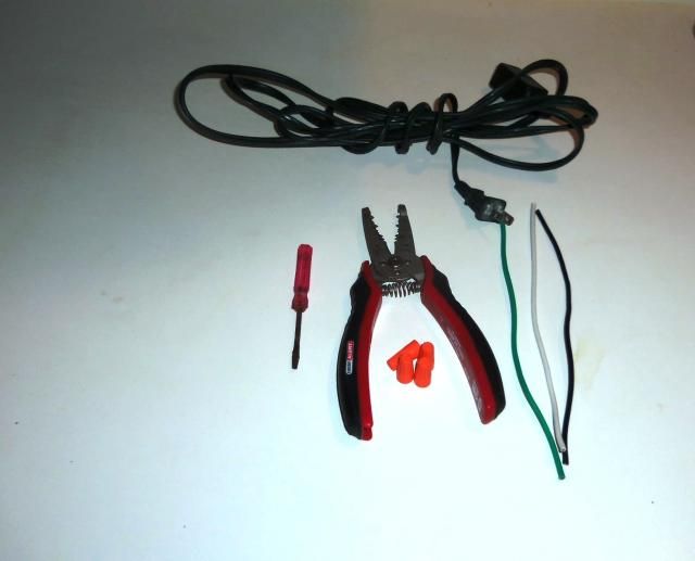
What your going to need:
Wire strippers
2-3 foot extension cord ($3.00 )
4 wire nuts
some small sections of wire (can be taken from extension cord)
Small flat head screw driver (ones for eye glass's work well)
Optional:
electrical tape
Project box (something to put the controller in)
Dremel with cut-off wheel or other plastic saw (for mounting the controller in certain applications)
Ex-President-North American Discus Association-NADA
[SIGPIC][/SIGPIC]
First step;
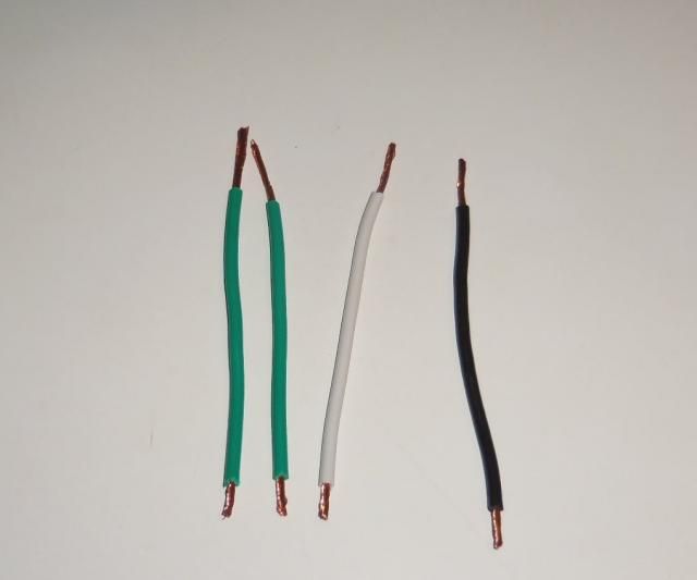
take 4 small pieces of wire (4-5") and bare the ends exposing the wire. Notice how I kept one end only about 3/8" bare-this will be the end that goes into the controller. The other end you can strip to about 1".
Ex-President-North American Discus Association-NADA
[SIGPIC][/SIGPIC]
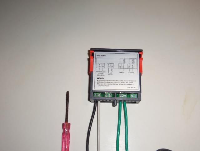
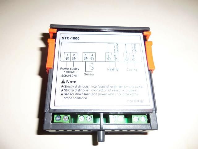
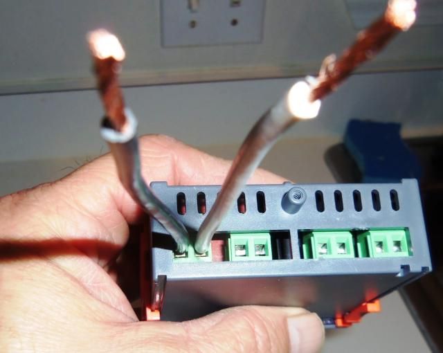
Insert two of the wires into the terminals marked "1" and "2".
Make sure you get all the wire into the terminal block and don't have any strands of wire possibly causing a short. After you have them inserted, tighten down the set screws snug. When done give the wires a little tug to make sure they are secure. You might have to first loosen the clamp to insert the wires.
Ex-President-North American Discus Association-NADA
[SIGPIC][/SIGPIC]
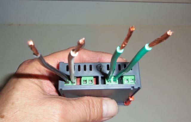
Repeat the steps inserting the last two wires into terminals 5 and 6. (terminals 3 & 4 are for the temperature probe, terminals 7 & 8 are not used unless you also want to operate a chiller).
Last edited by pcsb23; 12-02-2014 at 06:55 AM. Reason: at Ricks request
Ex-President-North American Discus Association-NADA
[SIGPIC][/SIGPIC]
Take the extension cord and cut it into two pieces, the male plug end (goes into the electric socket), and the female end (heater gets plugged into controller here). The length of each end will depend on where exactly your receptacle is, and where you plan on having the controller in relationship to your heater. Typically the male end is much longer while the female end is shorter, assuming the controller will be on or near the top of the tank.
I choose to use a cheap extension cord that uses 14 gauge wire. This should be more than suffice for up to 600 watts. If you plan on using the controller to control multiple heaters that exceed 600 watts, I would suggest using 12 gauge wire.
Last edited by nc0gnet0; 11-29-2014 at 05:24 AM.
Ex-President-North American Discus Association-NADA
[SIGPIC][/SIGPIC]
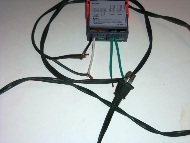
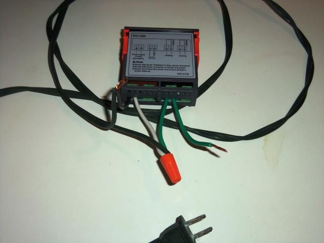
Take the plug end of the extension cord (with the ends stripped) and twist them onto the wires that we previously had connected to terminals 1 & 2. This will provide power to the unit.
Edited by Ricardo to add line from post #103
Find post #103 HereOriginally Posted by nc0gnet0

Last edited by rickztahone; 04-21-2015 at 11:44 PM.
Ex-President-North American Discus Association-NADA
[SIGPIC][/SIGPIC]
Ok, now the next couple of steps is where most people screw up. The controller is nothing more than an automated switch/relay that is controlled by the temperature you choose to have the circuit "on" (your heater). When the probe senses the temperature drop below a certain temperature it closes the switch (which is terminals 5 & 6 ) which allows power to flow to your heater allowing it to heat. When it gets to the desired temperature, it then opens, or turns off.
So, we need to bring power to the switch. We do this by connecting terminals 2 & 5 together. Take the wire from terminal 5 and twist it to the two wires already twisted together going to terminal 2. When done twist on a wire nut. I also like to then add some electrical tape to make sure the nut doesn't come off, this is optional but recommended.
Last edited by nc0gnet0; 11-29-2014 at 05:25 AM.
Ex-President-North American Discus Association-NADA
[SIGPIC][/SIGPIC]
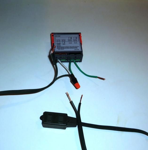
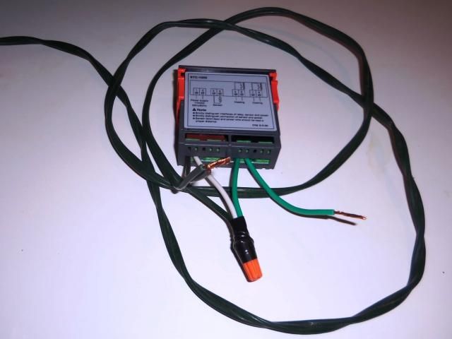
Now, as you can see, we only have two sections of bare wire left. We Also have to install the female end.
Take one end of the female plug and attach it to terminal 1 (the terminal with two wires twisted together) and the other end to terminal 6, using wire nuts and electrical tape.
Last edited by nc0gnet0; 11-29-2014 at 03:49 AM.
Ex-President-North American Discus Association-NADA
[SIGPIC][/SIGPIC]
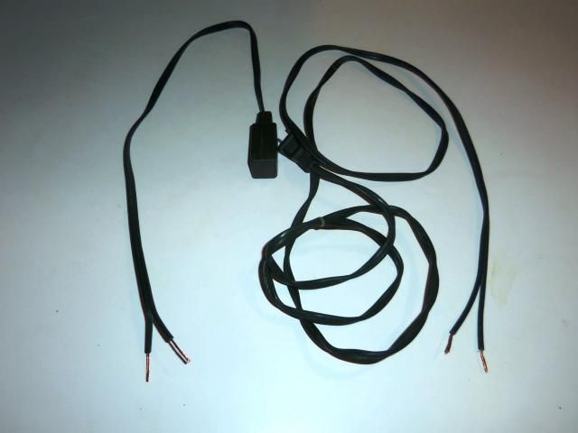
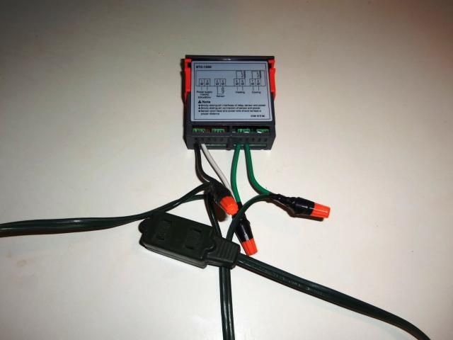
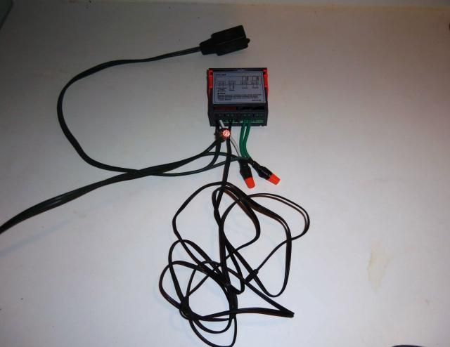
Now that the controller is wired up, we just need to insert the probe into terminals 3 & 4. this can be done first as well, however I choose to leave it until last to avoid confusing the wires.
Ex-President-North American Discus Association-NADA
[SIGPIC][/SIGPIC]
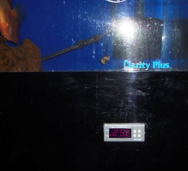
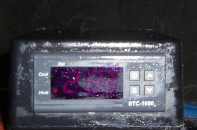
Ok, we are done, but we might want to install the device in some type of enclosure or mount it into a stand. (or we could just live dangerously and set it like this on the tank....just don't drop in in)
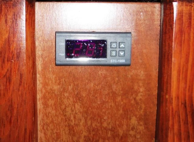
One option is the tank stand install:
The flash on my camera is making the display appear a lot dimmer than they are.
Last edited by nc0gnet0; 11-29-2014 at 04:33 AM.
Ex-President-North American Discus Association-NADA
[SIGPIC][/SIGPIC]
Calibration-Set-up.
1) To turn the unit on press and hold the button on the top left (circle with a line through it icon). To turn it off press and hold the button until the unit powers off (about three seconds).
2) To set desired temperature press and HOLD the "S" button. A F1 symbol will appear. While still holding the "S" button press and hold either the "^" arrow of the "down arrow". When you get to the desired temperature, release both buttons and hit the power button once. This will set the temperature the unit will maintain tank temperature at.
3) To set the temperature deviation (this is the amount of fluctuation the controller will allow before kicking on. Set this at the minimum value of 0.3. What this means is the controller will allow the temperature to fall .3 degrees Celsius before turning the heater on.). Once again press and hold the "s" button. When the F1 symbol appears, release the "S" button and hit the "up" arrow once, an F2 symbol should appear. Then press the "S" button and hold and adjust the setting to 0.3.
4) Calibrating the controller. If you have a thermometer that you know is correct, the controller unit can be calibrated to that thermometer. Just calibrate the controller up or down by pushing and holding the "S" key until the F1 symbol appears. Release the "S" button and using the up and down arrows cycle through the functions until you get to F4. Again press and hold the "S" button and either add or subtract the amount of degress you need to mach your trusted thermometer.
* The F3 function is only used if you are also using this unit to control a chiller.
Ex-President-North American Discus Association-NADA
[SIGPIC][/SIGPIC]
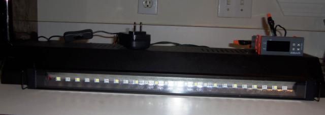
For this particular mount, I am going to combine two different things, the controller and a LED light strip by aquaticlife. You can buy these dirt cheap on ebay here:
. http://www.ebay.com/itm/Aquatic-Life...item3ce100f12f
http://www.ebay.com/itm/Aquatic-Life...item3a8f76ef81
Please don't ask me if they put out enough light for a planted tank....
They do put out plenty of light for a non-planted tank, at least as much as there fluorescent counterparts in similar size.
What I am going to do is use one of those plastic fluorescent hoods that we all have laying around, rip out the innards, and then mount both the light fixture and controller in to the hood.
Ex-President-North American Discus Association-NADA
[SIGPIC][/SIGPIC]

That's awesome! !! Definitely will give it a try. Thank you Rick.
 Posting Permissions
 |